

The final colour of each fragment is calculated in the vertex program and fragment program of the shader. These are calculations for atmosphere colour tint, general illumination of each vertex, edge illumination to account for the perspective, and blending of the atmosphere and planet surface. The shader uses simplifications assuming practically spherical planets, like the Earth.
Atmosphere colour
The atmosphere light was tinted with a gradient for angles 0 to 180 degrees from the centre of illumination, as described here.

General illumination
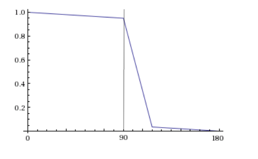
Only half of a spherical planet is directly illuminated by a directional light like sun light. Because of light scattering in the atmosphere, some light scatters into the other side of the planet. The graph below shows the general illumination intensity as a function of the degrees from the centre of illumination in my shader. The width of the big slump after the perpendicular angle can be adjusted, and is 27 degrees as default. The planet’s surface texture sampling is multiplied by this intensity. The overlayed atmosphere is multiplied by this intensity and also the perspective factor.
Edge illumination
Looking straight at a spherical planet with an atmosphere around it, one will see a longer distance through the atmosphere further towards the edges of the sphere. If the viewer can see longer through the atmosphere more light is scattered back towards the viewer, as it is scattered back from more points. This effect is the strongest at the very edges of the planet contour as the viewer can see right through the atmosphere without the view being obscured by the planet surface.

In my shader – instead of adding all the light going back through integration – I used a ramp function to increase the intensity of the atmosphere light according to the angle between the direction towards the viewer and the vertex’s normal.
float _FresnelExponent = 5; // default value
float angleNormalViewer = sin(acos(dot(normalDirection, viewDirection)));
float perspectiveFactor = 0.3 + 0.2 * pow(angleNormalViewer, _FresnelExponent) + 0.5 * pow(angleNormalViewer, _FresnelExponent * 20);
The last term will only give a big contribution for very perpendicular angles, i.e. right at the edge of the sphere. The closest sphere point to the viewer has 0 degrees between direction to viewer and normal, so the perspective factor will then be 0.3, signifying the least amount of atmosphere seen through and therefore less atmosphere intensity.

This perspective factor is then multiplied by the general illumination to calculate the intensity of the atmosphere at each vertex.
Specular reflection
The shader samples the alpha channel of the planet surface texture as fragment specularity. Basically, water is reflecting white sun light whereas land has only diffuse reflection. I use a Phong shader calculation for specular reflection. I had to do the specular calculation in the fragment shader to avoid a triangular look.
Surface and atmosphere combined
I developed the transparent atmosphere shader to be used on a bigger sphere around a sphere with an opaque shader of the planet surface. Since the Earth’s atmosphere is so close to the surface anyway, I thought it would be better to combine these two separate shaders into a shader for one surface – halving the vertex count. I used the same blending equation as traditional transparency to blend the calculated surface colour and the atmosphere.
In my Unity solution, either two spheres with surface or transparent atmosphere shaders can be activated or – as by default – the activated single sphere uses the opaque shader for both planet surface and atmosphere. Both setups work the same. The shader is ultimately only a visual approximation of atmospheric light scattering suitable for GPU-light hardware like mobile units, not a scientifically accurate simulation.

You must be logged in to post a comment.