
The shader is finished. I explained my method of displaying a light-weight facsimile of atmospheric scattering in the previous devlog post. I posted the shader source code here. Try out the shader viewer in your browser here. To download the whole Unity 5.4 project – with the shader files and executables for viewing the shader on Android (TV), Windows, and Linux – download the whole package here.
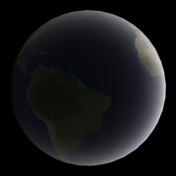
The method of visualising the planet atmosphere
The final colour of each fragment is calculated in the vertex program and fragment program of the shader. These are calculations for atmosphere colour tint, general illumination of each vertex, edge illumination to account for the perspective, and blending of the atmosphere and planet surface. The shader uses simplifications assuming practically spherical planets, like the Earth.
Atmosphere colour
The atmosphere light was tinted with a gradient for angles 0 to 180 degrees from the centre of illumination, as described here.

General illumination
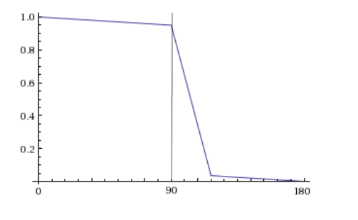
Only half of a spherical planet is directly illuminated by a directional light like sun light. Because of light scattering in the atmosphere, some light scatters into the other side of the planet. The graph below shows the general illumination intensity as a function of the degrees from the centre of illumination in my shader. The width of the big slump after the perpendicular angle can be adjusted, and is 27 degrees as default. The planet’s surface texture sampling is multiplied by this intensity. The overlayed atmosphere is multiplied by this intensity and also the perspective factor.
Edge illumination
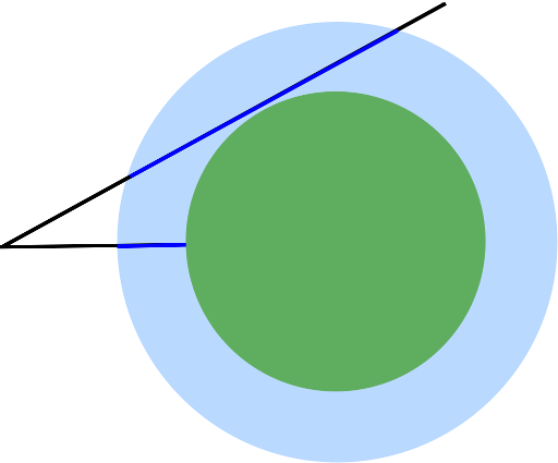
Looking straight at a spherical planet with an atmosphere around it, one will see a longer distance through the atmosphere further towards the edges of the sphere. If the viewer can see longer through the atmosphere more light is scattered back towards the viewer, as it is scattered back from more points. This effect is the strongest at the very edges of the planet contour as the viewer can see right through the atmosphere without the view being obscured by the planet surface.
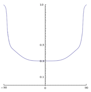
In my shader – instead of adding all the light going back through integration – I used a ramp function to increase the intensity of the atmosphere light according to the angle between the direction towards the viewer and the vertex’s normal.
float _FresnelExponent = 5; // default value
float angleNormalViewer = sin(acos(dot(normalDirection, viewDirection)));
float perspectiveFactor = 0.3 + 0.2 * pow(angleNormalViewer, _FresnelExponent) + 0.5 * pow(angleNormalViewer, _FresnelExponent * 20);
The last term will only give a big contribution for very perpendicular angles, i.e. right at the edge of the sphere. The closest sphere point to the viewer has 0 degrees between direction to viewer and normal, so the perspective factor will then be 0.3, signifying the least amount of atmosphere seen through and therefore less atmosphere intensity.
This perspective factor is then multiplied by the general illumination to calculate the intensity of the atmosphere at each vertex.
Specular reflection
The shader samples the alpha channel of the planet surface texture as fragment specularity. Basically, water is reflecting white sun light whereas land has only diffuse reflection. I use a Phong shader calculation for specular reflection. I had to do the specular calculation in the fragment shader to avoid a triangular look.
Surface and atmosphere combined
I developed the transparent atmosphere shader to be used on a bigger sphere around a sphere with an opaque shader of the planet surface. Since the Earth’s atmosphere is so close to the surface anyway, I thought it would be better to combine these two separate shaders into a shader for one surface – halving the vertex count. I used the same blending equation as traditional transparency to blend the calculated surface colour and the atmosphere.
In my Unity solution, either two spheres with surface or transparent atmosphere shaders can be activated or – as by default – the activated single sphere uses the opaque shader for both planet surface and atmosphere. Both setups work the same. The shader is ultimately only a visual approximation of atmospheric light scattering suitable for GPU-light hardware like mobile units, not a scientifically accurate simulation.
How to make a simple space skybox with sun in Unity
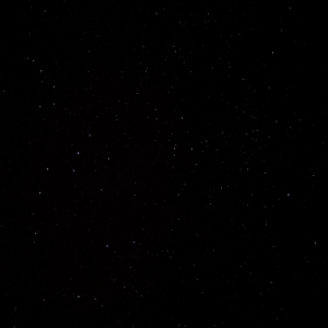
 In the Unity menu click Assets > Create > Material and in the material’s inspector, select Skybox > 6 Sided as shader. For all six texture slots you assign a space textures by dragging them into each slot. You can use this CC0-licensed public domain star sky texture for all of them if you are fine with subtly repeating stars. Open the texture’s import settings and set the Wrap Mode to Clamp and Apply.
 Download full resolution here.
In your camera object properties, set Clear Flags to Skybox. In Unity the menu, select Window > Lighting and select the material you created as Skybox under the Environmental Lighting section of the Scene section of the Lighting box. 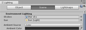
Voilà! You have a starry skybox. To add a sun, create a lens flare object with Assets > Create > Lens Flare. For Flare Texture use a sun texture without alpha channel – for example this CC0-licensed public domain sun sprite I made. Set Texture Layout to 1 Texture, Size to 10, Color to white, and check Zoom and Fade.
![]() Download full resolution here.
Download full resolution here.
Add a lens flare component to your directional light with Add Component > Effects > Lens Flare. Select the lens flare you created in the Flare property and check Directional. You can set Fade Speed to 50. Now you should have a nice looking starry skybox with a sun that follows your directional light.
The colour of the sky
The outer layers of the atmosphere contain aerosols that don’t reflect light rays. When light hits aerosols they are refracted in different directions depending on what part of the aerosol they hit. Since there is an innumerable amount of aerosols in the atmosphere and infinite light rays, as they pass through the aerosols they are eventually scattered in all directions. This light scattering is called Rayleigh scattering. The sun’s white light is refracted more or less depending on the light’s wave lengths. That means the light colours are scattered more or less, and are thereby separated.
In inner atmosphere there are also dust particles (like sand etc.) that are too big and opaque to refract, but instead reflect light. This is called Mie scattering. Mie scattering does therefore not alter the light colour, so it is more white. I decided to only implement Rayleigh scattering since this is the most interesting part of atmospheric light scattering. I also did not include clouds in my visualisation.
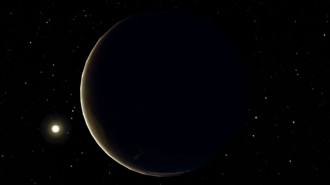
Only half of a planet is directly illuminated by the sun. Each photon changes direction each time it randomly hits an aerosol. Theoretically it could thereby be refracted along the planet’s curve every time to circle around the whole planet several times. Of course that is not very likely but considering the theoretical infinite number of light rays, it does happen. From around 90 degrees from the centre of the illuminated half some light scatters around to the dark side of the planet – but it fades quickly.
Only light that is scattered back to the viewer is visible as light in the atmosphere. The blue light scatters most, so more blue light is scattered in the direction of the viewer than green, yellow, and red. That means that atmospheric light in the directly illuminated half of the planet has a blue-ish tint. Like-wise, as blue scatters away more aggressively, there is less blue left in the fringes of the illuminated half of the planet – “where the sun rises or sets”. That is why the atmosphere is more yellow and red where the sun does not directly illuminate.
I thought about many ideas for how to implement this in a shader. One idea was to have separate equations for each of the RGB channels. I decided to instead tint the final light with a look-up table of a light colour gradient in the form of a one-dimensional texture. The light colour gradient was made from an actual photo of light spectrum from aerosol-refracted sun light, modified to have around the same brightness value across the gradient. I sampled the colour left to right in proportion to the angle 0-180 degrees from the planet’s centre of illumination. Since the light intensity is modified by all colours other than multiplication with white, I multiplied with the inverse of the sample colour’s brightness.

Android TV & OpenGL ES 2 constraints
I am testing on my only Android device, the Amazon Fire TV Stick. The SOC Broadcom Capri 28155 was low-end a few years ago, but modern low-end smartphones have surpassed it in terms of performance and shader model capabilities, which makes it a good candidate to test the shader’s performance on. It is an Android TV compatible device that plugs into a TV HDMI port so it naturally lacks touch screen input. It is controlled with the simple remote for the Amazon Fire TV Stick that is basically like the standard Android TV remote with an extra Android menu button – the same amount of buttons as the Android TV Mini-Controller.
The device only supports up to 2K textures so that resolution was used for the surface texture. I wanted to tint the atmosphere using texture sampling in the vertex shader for performance but had to move it to the fragment shader since the tex2dlod function was not implemented in OpenGL ES 2.0.
I did not use very complicated controls for viewing the planet on Android TV. The remote D-pad is used to rotate the camera around the planet horizontally and vertically. I tried using the D-pad middle button to switch between rotating the camera and planet (so that the light could hit the Earth with different angles) but it was very confusing. I left these controls on the arrow keys for PC, but added a script I found online for more free WASD and mouse controls. The R and F keys can be used to go up and down as well for better 3D controls. For Android smartphone devices I added gyro controls for rotation and made the touch screen work as the mouse look-around controls, but I could not test that on an actual smartphone.
Fast facsimile of atmospheric scattering
I reviewed papers and materials on accurately visualising atmospheric scattering according to Nishita’s algoritm. These algorithms require integration upon integration to sum up all the light that is scattered in the direction of the viewer for every vertex and therefore very computationally heavy. I tried an optimized one – with a fast lookup table and only one intensity channel – and it only ran at 90 FPS on my 2015 CPU Intel Core i7-6500U. It would run too slow on the modest Android hardware I am aiming for.
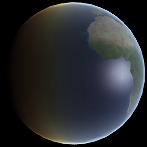
I studied the visualisations to find features that could be replicated. I made another sphere with a transparent shader with a size relative to the planet similar to the outer atmosphere radius (6 471 km) and the Earth radius (6 371 km). My plan is that the outer sphere’s shader should replicate the atmosphere lighting’s features (multi-scattering), and the planet surface shader should replicate the Earth surface’s reflection (single-scattering). I started working on the atmosphere shader and used a Unity diffuse shader for the planet surface for now.
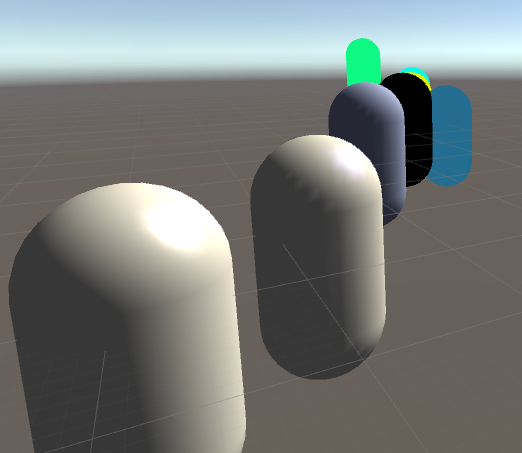
My first version was a Fresnel shader to simulate the longer length of atmosphere the viewer sees towards the edges of the planet. With just this shader, the edges of the planet were always lit from all directions regardless of sun position, as seen above. This was multiplied by a diffuse shader that lit up even obtuse angles to simulate the light scattering around into the unlit half of the planet.
Shader practise
I have made flat shaders, Lambertian shaders, and Phong shaders. I also learnt to do it on a per-vertex basis and per-pixel basis for speed or smooth result.
HLSL variable woes
Whereas the OpenGl context in GLSL provides global variables for different aspects, input and output variables must be strictly defined in HLSL. Unity does provide some set variables for easier integration with the graphics engine, like _WorldSpaceLightPos0 for the light position. For a scalar variable I had correctly written Float in ShaderLab properties but float4 (4 dim vector) in the CGPROGRAM section. Faire attention SVP!
GLSL not a good fit for Unity on PC
I have decided to write my shader in HLSL/Cg rather than GLSL. On my Windows PC, Unity assumes that I that the GLSL I am writing is version 4 (that my graphics card supports) but can’t compile as all the resources I find are based on GLSL version 1.3 or lower but as of 1.4 the oft-used type qualifiers attribute and varying were removed. My Android device has OpenGL ES 2.0 hardware which supports only GLSL version 1.1 and parts of 1.2. That means the same code will not run on both my PC for debugging purposes and on my Android device. I have only been able to make simple shaders without portability problems. Also, Unity does not recommend writing directly in GLSL. The Unity editor crashed and froze many times without producing helpful debug messages about the GLSL code errors.
Combining Cg/HLSL and GLSL in Unity
When you have never programmed shaders before, there is quite a lot to decide on. Documentation and tutorials focus on a specific shader language, so even though the concepts might transfer one should make sure to pick the right one. My target is an Android device with support for OpenGL ES 2.0 and that uses GLSL for shaders. Normally HLSL is not portable and only runs on DirectX platforms. While there are compilers from the deprecated language Cg to both Direct3D HLSL and GLSL, Unity 5 actually uses an adaption of HLSL that runs as HLSL for Windows and Xbox One platforms and compiles to GLSL for other OpenGL platforms. One can also write GLSL in Unity, but then it will not be able to recompile that to other platform-specific languages and it will only run on GLSL compatible platforms.
I have not yet decided whether I want to write my shader in GLSL or HLSL/Cg (Cg and HLSL practically only have subtle differences and are almost syntactically identical as they were co-developed by Nvidia and Microsoft and released with different platform support). It will depend on which languages the learning resources that will help me write my shader use. Unity tutorials and documentation favours HLSL for portability reasons but writing directly in GLSL might make for faster shaders on Android.
Unity’s ShaderLab language is a shader specification format like CgFX. The actual code for running the shader program is written in Cg/HLSL/GLSL, and nested in ShaderLab code. When you create a new shader file in Unity 5 – with for example the command Assets > Create > Shader > Unlit Shader – that file contains both ShaderLab code and Cg/HLSL/GLSL code. A shader file can contain different implementations of the shader, for example in both GLSL and HLSL, and ShaderLab can be used to set graphics device states and expose settable variables in Unity. All the file’s code that is not written in ShaderLab is nested within the keywords CGPROGRAM and ENDCG for Cg/HLSL and GLSLPROGRAM and ENDGLSL for GLSL. Mixing the shader program languages can be done by making two SubShader blocks in ShaderLab – one for each. The first SubShader that can be run on the platform will be used. Normally Unity cannot run GLSL shaders on Windows – not even for testing – but if the Unity Editor exe is started with the argument -force-opengl it will force Unity to run in OpenGL mode. This can be accomplished by making a shortcut to the editor exe and changing the target from “[Path]\Unity.exe”to “[Path]\Unity.exe” -force-opengl.
We can exchange all the code in the Unlit shader file that we made for this simple flat single-colour shader.
Shader "Custom/Test1Combo - Flat Color"
{
	Properties
	{
		_Color("Color", Color) = (1,1,1,1)
	}

	SubShader
	{
		Pass
		{
			GLSLPROGRAM

			// includes
			#include "UnityCG.glslinc"

			// user-defined variables
			uniform lowp vec4 _Color;

			// vertex program
			#ifdef VERTEX
			void main() {
				gl_Position = gl_ModelViewProjectionMatrix * gl_Vertex;
			}
			#endif

			// fragment program
			#ifdef FRAGMENT
			void main() {
				gl_FragColor = vec4(1.0, 0.6, 0.0, 1); // = _Color;
			}
			#endif

			ENDGLSL
		}
	}

	SubShader
	{
		Pass
		{
			CGPROGRAM
			// pragmas and includes
			#pragma vertex vert
			#pragma fragment frag

			#include "UnityCG.cginc"

			// user-defined variables
			uniform float4 _Color;

			// base input structs
			struct vertexInput
			{
				float4 vertex : POSITION;
			};

			struct vertexOutput
			{
				float4 pos : SV_POSITION;
			};

			// vertex program
			vertexOutput vert(vertexInput v)
			{
				vertexOutput o;
				o.pos = mul(UNITY_MATRIX_MVP, v.vertex);
				return o;
			}

			// fragment program
			float4 frag(vertexOutput i) : COLOR
			{
				return _Color;
			}

			ENDCG
		}
	}
	//TODO decomment fallback when testing is finished
	//Fallback "Diffuse"
}
It exposes the Color parameter to the Unity editors material properties in the ShaderLab block Properties. So if one were to create a 3D object, create a new material and attach it to the 3D object, and set that material to use the shader Custom > Test1Combo – Flat Color, then the 3D object should be coloured in the material’s selected colour. That is running the Cg SubShader though. We can test a GLSL SubShader by having it first and making it different from the Cg/HLSL SubShader – just like in the code above. You can see that the colour is hard-coded to orange in the GLSL SubShader. Closing Unity and opening it up in forced OpenGL mode should change the colour of the object from the selected colour to orange. If that works then Unity is running the GLSL shader. Of course it would be best to then correct the hard-coding and setting gl_FragColor = _Color; instead so both the GLSL and HLSL SubShaders do the same thing.
You can read about how to write HLSL/Cg shaders in Unity’s documentation and this tutorial series, and GLSL shaders in this Cambridge lecture and here and here.

You must be logged in to post a comment.